Every weekend across America, DIY mechanics and local tire shops prepare for routine maintenance, seasonal tire swaps, or quick brake inspections. You slide the heavy steel frame under the chassis, pump the handle, and hear a faint metallic groan as the suspension settles. Most drivers assume this is just the normal sound of a vehicle shifting its weight. In reality, it is often the sound of a catastrophic, invisible failure. A deeply ingrained habit—the belief that lifting a car as close to the tire as physically possible provides the most stability—is actually the fastest way to cause permanent, hidden damage.
This seemingly harmless technique is secretly destroying the structural integrity of modern vehicles. A critical miscalculation during this routine process puts immense, concentrated pressure in exactly the wrong place, leading to microscopic but permanent warping of expensive components. The true culprit isn’t the overall weight of the car, nor is it a defective part. Instead, it is a fundamental misunderstanding of structural geometry and load distribution that ruins your ride quality long before you even realize what happened.
The Hidden Physics of Wheel Barrel Distortion
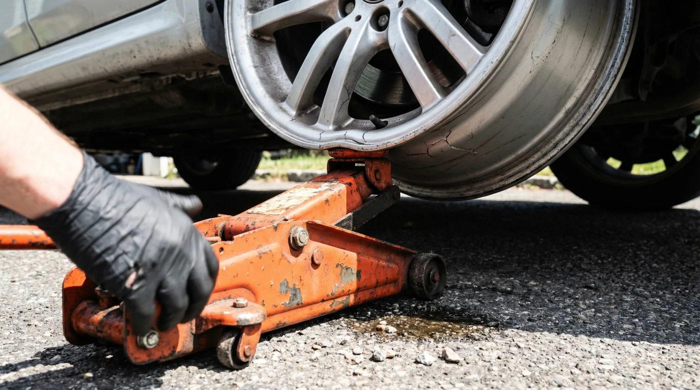
The foundational error occurs when a Hydraulic Floor Jack is positioned improperly under a lower control arm or an unreinforced section of the chassis near the wheel hub. As the vehicle rises, the arc of the jack’s lifting arm changes the geometric angle of the vehicle’s suspension. If the jack saddle slips or shifts, the load vector transfers directly onto the inner rim lip of the wheel. Modern aluminum-magnesium alloy wheels are engineering marvels designed to bear immense weight from the center hub outward to the road, but they possess surprisingly little resistance to lateral crush forces applied to the inner barrel. When thousands of pounds of pressure pinch the lower edge of the barrel, the metal permanently deflects.
- Symptom: Unexplainable steering wheel vibration at 65 mph = Cause: Micro-warping of the inner wheel barrel from off-axis jacking stress that disrupts the rotational balance.
- Symptom: Slow, mysterious tire pressure loss = Cause: A bent inner bead seat compromising the airtight seal between the rubber tire and the alloy rim.
- Symptom: Accelerated inner tread wear = Cause: Jack-induced camber distortion and bent suspension knuckles altering the precise alignment of the vehicle.
| Maintenance Approach | Mechanism of Action | Long-Term Vehicle Impact |
|---|---|---|
| Traditional Close to Wheel Lifting | Concentrates load on lower control arms; risks jack saddle contact with inner barrel. | High risk of lateral runout, micro-fractures in alloy, and destroyed tire bead seals. |
| Factory Pinch Weld Lifting | Distributes weight along the reinforced structural sills designed for vertical loads. | Zero risk to unsprung suspension components; preserves wheel geometry perfectly. |
| Crossmember Center Lifting | Lifts the entire axle evenly, keeping suspension components static. | Ideal for fluid changes; entirely isolates the wheels from direct mechanical stress. |
To truly understand why this specific distortion happens so rapidly, we must look at the exact forces acting on your vehicle’s unsprung weight during a lift.
The Science of Stress Vectors and Alloy Failure
- Subaru Outback drivetrains shatter when owners mix different replacement tire brands
- 3M adhesive wheel weights secretly detach during automated car wash cycles
- Magic Eraser sponges microscopically scratch protective clear coats off alloy wheels
- AAA roadside assistance crews officially stop plugging punctured tires on highways
- Goodyear quietly discontinues popular standard passenger tires favoring electric vehicle compounds
For proper dosing of force and motion, always maintain a minimum clearance of 3.5 inches between the edge of the jack saddle and the inner wheel barrel. When lifting, ensure the ambient garage temperature is not causing hydraulic fluid viscosity drops (ideally operating above 45 degrees Fahrenheit), and strictly limit the lift speed to 1 inch per second to prevent sudden load shifts.
| Alloy Component | Load Threshold (Radial) | Load Threshold (Lateral/Shear) | Failure Mechanism |
|---|---|---|---|
| Inner Barrel Lip | Up to 3,500 lbs | Fails at 450 lbs | Plastic deformation resulting in permanent flat-spotting. |
| Center Hub Face | Over 5,000 lbs | Up to 2,000 lbs | Resilient; safely handles torque and direct bolt compression. |
| Outer Wheel Spoke | Up to 4,000 lbs | Fails at 800 lbs | Micro-cracking at the base of the spoke from offset torsion. |
Armed with the hard data on how quickly an expensive alloy wheel can fail under improper loads, you need a bulletproof protocol to prevent this damage in your own garage.
The Ultimate Protocol for Damage-Free Lifting
Studies confirm that a vast majority of driveway wheel damage is entirely preventable with the implementation of strict mechanical protocols. Relying solely on a bare metal jack saddle is the primary vector for component destruction. To eliminate the risk of transferring force to the wheel barrel, you must upgrade your contact points and fundamentally change your approach to vehicle elevation.
The Top 3 Rules for Precision Lifting
- Step 1: The Perpendicular Rule. Your Hydraulic Floor Jack must be positioned at an exact 90-degree angle to the vehicle’s designated lifting point. An angled jack will pull the vehicle horizontally as it rises, dramatically increasing the chance of the saddle sliding into the wheel barrel.
- Step 2: The Polymer Buffer. Never allow bare steel to touch bare metal. Utilize a high-density polyurethane jack pad or a slotted rubber puck. This compresses under the 1,500-pound load, gripping the pinch weld and locking the jack in place to prevent lateral drift.
- Step 3: The Clearance Verification. Before pumping the handle past the initial suspension droop, pause. Visually verify there is a minimum of 4 inches of clearance between the jack’s chassis and the inner wheel lip. As the suspension decompresses, the wheel will arc inward; you must account for this geometric shift.
| Equipment / Practice | What to Look For (Safe) | What to Avoid (Dangerous) |
|---|---|---|
| Jack Saddle Pad | Deep-slotted, reinforced polyurethane rated for 3+ tons. | Hard plastic, cracked rubber, or bare steel saddles with sharp teeth. |
| Placement Location | Factory-designated pinch welds, subframe crossmembers, reinforced differentials. | Hollow lower control arms, trailing arms, or directly under the shock mount. |
| Jack Mechanism | Dual-piston hydraulic systems for smooth, incremental lifting. | Single-piston jacks that jerk upward or slowly bleed pressure during positioning. |
Mastering these specific tools and techniques ensures your wheels stay perfectly round, but there is one final diagnostic check every master mechanic relies on before removing the safety stands.
The Post-Lift Diagnostic Verification
Even with the best precautions, verifying the integrity of your work is the hallmark of a professional. Once the vehicle is safely secured on jack stands, experts advise performing a rapid radial runout test. With the transmission in neutral (and wheels chocked), spin the elevated wheel by hand. Watch the gap between the inner wheel lip and a fixed point on the suspension. If you observe a variance or wobble exceeding 0.03 inches, the barrel has suffered lateral deflection. Catching this early allows for professional wheel straightening before the compromised bead seat causes a high-speed tire blowout. Protecting modern aluminum-magnesium alloy components requires more than just brute strength; it requires absolute precision.
Applying these professional standards guarantees your driveway maintenance protects your performance investment instead of quietly costing you thousands in ruined wheels.